This article serves as a reference document for the user to set up and test for Over Current Protection (OCP) and generate Current-Voltage (I-V) curve plots for the Source UUT (Unit Under Test) using the GRL Power Suite Pro (GRL-PSP) software and the GRL-USB-PD-C2 USB Type-C Test Controller Hardware / GRL-USB-PD-F1 USB Power Performance Tester.
Note: For details on using the GRL-PSP software or the GRL-USB-PD-C2 / F1 Controller, please refer to their respective user documentation on GRL's website.
Search for Source Over Current Protection Thresholds and Identify Voltage-Current Relationship Problems
The ‘IV Curves’ Test Case allows the user to determine the Over Current Protection (OCP) thresholds and generate Current-Voltage (I-V) curve plots for the Source UUT that is connected to either USB Test Port 1 or Port 2 or both of the GRL-USB-PD-C2 / F1 Controller.
The GRL-PSP first negotiates a power contract for every PDO supported by the UUT, and increases the load gradually to find the threshold where OCP kicks in and voltage and current start to drop for safety reasons.
Here are the steps to set up and perform the OCP & IV curve test:
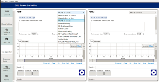
Figure 1: Select OCP & IV Curves Test Case
- On the Test Operation screen, select the OCP & IV Curves test from the drop-down menu.
- Connect a Source UUT to either USB Test Port 1 or Port 2 or both of the GRL-USB-PD-C2 / F1 Controller.
- Select the ‘1) Get PD source caps’ button to acquire Source PDO’s supported by the connected UUT.
- When the Source PDO’s are listed, select any of these PDO’s to request from the UUT to test for I-V curves.
- Set the fast and slow current steps which will be used during the test run to search for the OCP threshold limit.
- Set the delay between PDO transitions and starting OCP value.
- Select the Play button for the Test Port(s) attached with the UUT to start the test run. Note: You can right-click this button to access more ‘Play’ or ‘Stop’ functionality as desired.
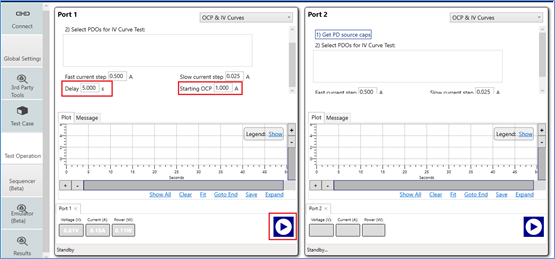
Figure 2: Set Delay & Starting OCP Values and Run Test
The test will execute for all the PDO's and increment the current until the OCP is triggered.
When the test run has completed, it will report out all the PDO's supported by the UUT and their OCP thresholds (under the OCP & IV Curves tab). The test results will also produce an I-V curve which graphically shows the relationship between voltage and current for each PDO. For many UUT’s that support PPS (Programmable Power Supply), current fold-back behavior may be reflected through the I-V curve where as the current increases beyond the OCP threshold, the voltage starts to curve/bend down rather than immediately shutting off. For UUT’s with non-PPS support, the voltage will most likely shut off immediately once the current increases beyond the OCP threshold.