This article describes the EPR protocol flow with respect to the compliance test
specification using the GRL-USB-PD-C2-EPR Browser Application for the Source (SRC) and Sink (SNK) DUT's.
EPR Protocol Flow for the SRC DUT
- During the initial BringUP.Procedure, the DUT initiates the SRC_Capability message and the GRL-USB-PD-C2-EPR tester hardware checks whether the Bit[23]:EPR mode Capable bit is set to 1 or not.

- The SRC_DUT and GRL-USB-PD-C2-EPR tester hardware then establish an explicit PDC contract.
The EPR Entry processes the DUT as a Source:
-
- The GRL-USB-PD-C2-EPR tester hardware initiates the EPR_Enter Mode Data Object with the Action field set to 1 and the DATA field set to 140W.

- The SRC_DUT responds with the EPR_Enter_Acknowledged Mode Data Object message with the Action field set to 2.

- The SRC_DUT initiates the Vendor_DISC_ID message in the SOP1 packet where the GRL-USB-PD-C2-EPR tester hardware is responding with the DISC_ACK message as follows:

- The GRL-USB-PD-C2-EPR tester hardware initiates the EPR_Enter Mode Data Object with the Action field set to 1 and the DATA field set to 140W.
-
-
- Bit[6:5]: VBus_Current handling_Capacity is set to 5A
- Bit[10:9]: Maximum VBUS voltage is set to 50A
- Bit[17]: EPR mode capable bit is set to 1
-
-
- The SRC_DUT initiates the EPR_Successed mode data object with the Action field set to 3.

- The SRC_DUT initiates the EPR_SRC_Capability message with the supported PDOs. If the SRC_DUT does not initiate all the SRC_Supported PDOs in its SRC_Cap message, the GRL-USB-PD-C2-EPR tester hardware sends the EPR_SRC_Capability message with the Chunk_request message in order to obtain all SRC_Supported PDOs (including EPR_PDOs).
The SRC_DUT then initiates the EPR_SRC_Capability message with all supported PDOs. - Now the SRC_DUT and GRL-USB-PD-C2-EPR tester hardware establish EPR negotiation using the COMMON.PROC.PD3.2.

- COMMON.PROC.PD3.2:-
- The SRC_DUT initiates the EPR_Successed mode data object with the Action field set to 3.
-
-
-
-
- The GRL-USB-PD-C2-EPR tester hardware is sending the EPR_Request message as follows:
Object Position
i. For EPR_Source_Cap message with no EPR PDO, Object Position = 001b
ii. For EPR_Source_Cap message with EPR PDOs, Object Position = 1000b
B27 (GiveBack Flag) = 0b
B26 (Capability Mismatch) = 1b
B25 (USB Communication Capable) = 0b
B24 (No USB Suspend) = 1b
B19…10 (Operating Current) = 100mA
B9…0 (Maximum Operating Current) = 100mA
- The SRC_DUT initiates the ACCEPT message.
- The GRL-USB-PD-C2-EPR tester hardware checks that the PS_RDY message is received from the DUT within the tPSTransition(1020ms) max from the last bit of the EOP of the Accept message.

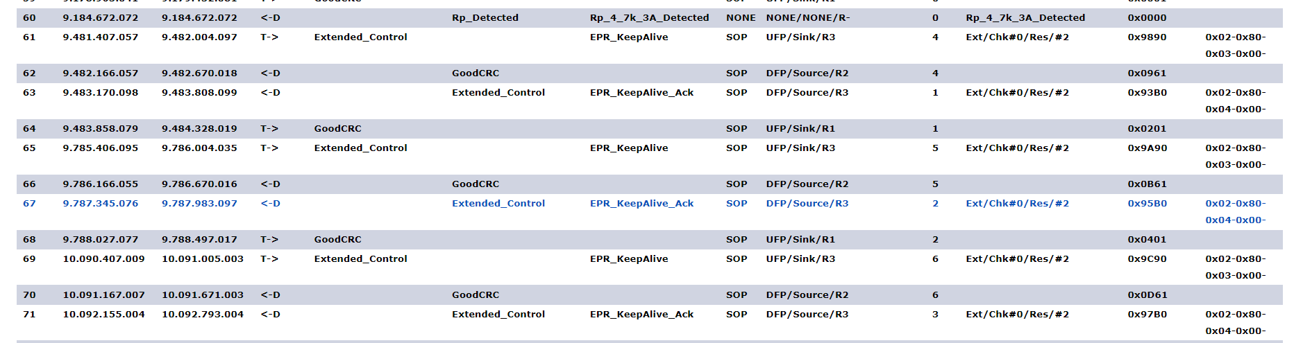
- The GRL-USB-PD-C2-EPR tester hardware sends the EPR_KeepAlive message for every tSinkEPRKeepAlive max (500ms).
- The GRL-USB-PD-C2-EPR tester hardware checks that the DUT responds with EPR_KeepAlive_Ack.
- The GRL-USB-PD-C2-EPR tester hardware is sending the EPR_Request message as follows:
-
-
-
Note: The EPR_KeepAlive message indicates that both the DUT and GRL-USB-PD-C2-EPR tester hardware are engaging in the EPR contract.
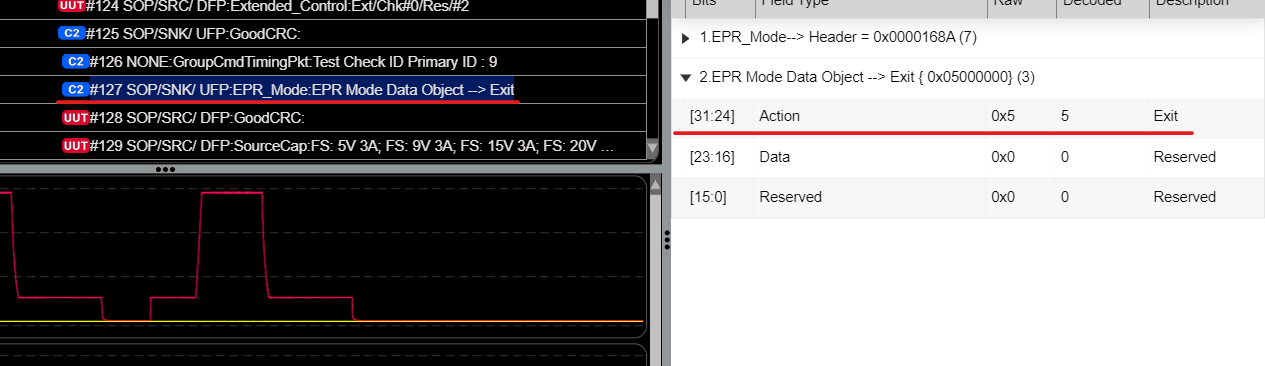
The SRC_DUT can initiate the EPR_Exit mode data object with the Action field set to 5 in order to exit from the EPR_Negotiation or otherwise the GRL-USB-PD-C2-EPR tester hardware can initiate the EPR_Exit mode data object with the Action field set to 5.
The SRC_DUT sends the SRC_Cap message within tFirstSourceCap (250ms) as an
acknowledgment to the EPR_Mode (Exit) message.
The SRC_DUT performs the SPR negotiation using COMMON.PROC.PD.10 as follows:
-
- The GRL-USB-PD-C2-EPR tester hardware sends a Request message for 5V at 100mA.
- B30 (Object Position) = 001b
- B27 (GiveBack Flag) = 0b
- B26 (Capability Mismatch) = 1b
- B25 (USB Communication Capable) = 0b
- B24 (No USB Suspend) = 1b
- B19…10 (Operating Current) = 100mA
- B9…0 (Maximum Operating Current) = 100mA

- The check Fails if an Accept message is not received.
- The check Fails if the PS_RDY message is not received within tPSTransition(550ms) max from the last bit of the EOP of the Accept message.
- The GRL-USB-PD-C2-EPR tester hardware sends a Request message for 5V at 100mA.
EPR Protocol Flow for the SNK DUT
- During the initial BringUp.Procedure, the SNK_DUT responds with the Request message for the SRC_Cap message by the GRL-USB-PD-C2-EPR tester hardware.
- The GRL-USB-PD-C2-EPR tester hardware checks that Bit[22]:EPRModeCapable is set to 1.
The EPR Entry processes the DUT as a Sink:
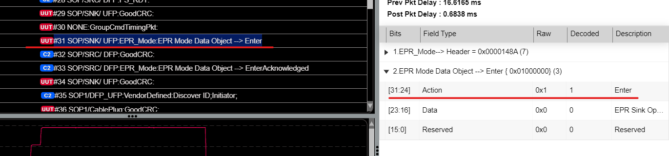
- The SNK_DUT initiates the EPR_Enter Mode Data Object with the Action field set to 1.
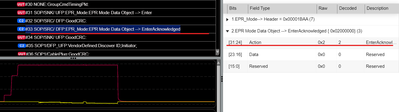
- The GRL-USB-PD-C2-EPR tester hardware as a SRC responds with the EPR_Enter_Acknowledged Mode Data Object message with the Action field set to 2.
- The GRL-USB-PD-C2-EPR tester hardware sends the EPR_Enter Successed Mode message with Action field set to 0x03(Enter_Succeeded) and Data field set to 0x0 within tEnterEPR (450ms) minimum from the EPR_Mode(Enter) message.

- The GRL-USB-PD-C2-EPR tester hardware sends the EPR_Source_Capabilities message after 50ms from the last bit of the GoodCRC message acknowledging the EPR_Mode (Enter_Succeeded) message and establishes EPR contract using common procedure COMMON.PROC.PD3.3 from Step 2.

- The GRL-USB-PD-C2-EPR tester hardware sends the EPR_Source_Capabilities message that contains eight PDO’s and one PDO (140W AVS_APDO).
- The check Fails if the DUT does not respond with an EPR_Request message.
- The GRL-USB-PD-C2-EPR tester hardware responds with an Accept message to the EPR_Request message.
- If the VBUS voltage is stable within the target voltage, the GRL-USB-PD-C2-EPR tester hardware sends a PS_RDY message at tPSTransition.EPRMode (830ms) min after the reception of the Accept message.

- The DUT should send every single EPR_KeepAlive message in above step or else this
check is updated as a warning.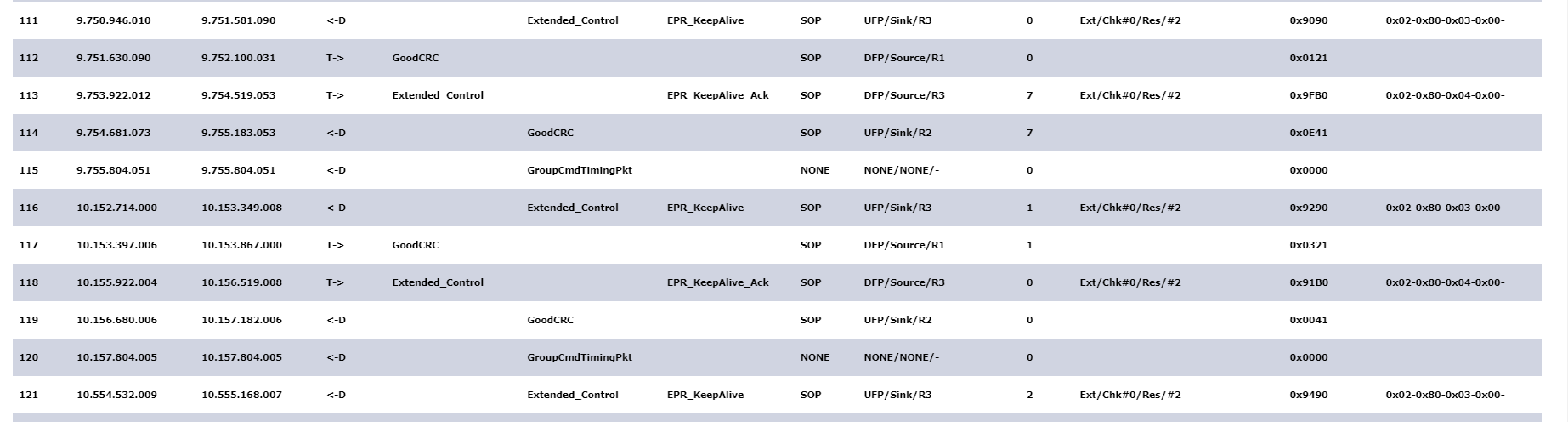
- The GRL-USB-PD-C2-EPR tester hardware waits for 100ms for the DUT to initiate the EPR_EXIT Mode message with Action field set to 5 and Data field set to 0, or else the GRL-USB-PD-C2-EPR tester hardware sends the EPR_EXIT Mode message with Action field set to 5 and Data field set to 0.
- The GRL-USB-PD-C2-EPR tester hardware sends a SRC_Cap message with SPR_PDOs to exit from the EPR contract and checks whether or not the DUT is responded with a Request message.
- The GRL-USB-PD-C2-EPR tester hardware and SNK_UUT establish a SPR_contract negotiation using COMMON.PROC.PD.10.
TEST.PD.PS.EPR.SRC3.1 Multiple EPR Request Load Test:
The GRL-USB-PD-C2-EPR tester hardware draws the Load current from 0% to 100% to 0% with the step increment of 25% of Load current from the max current in the EPR_PDOs supported by the SRC_DUT, as shown in the following example:
TEST.PD.PS.EPR.SRC3.2 PDO Transitions in EPR Mode:
The GRL-USB-PD-C2-EPR tester hardware requests different PDO's supported by the SRC_DUT based on the PDO transition table to check whether or not the SRC_DUT provides VBUS as expected, as shown in the following example: